Welcome to TeardropForum.com › Forums › Teardrop Builders’ Forum › Electrical Installation
- This topic has 6 replies, 4 voices, and was last updated 3 years, 11 months ago by
jklancke.
-
AuthorPosts
-
March 31, 2017 at 9:53 am #692
SOMDTD
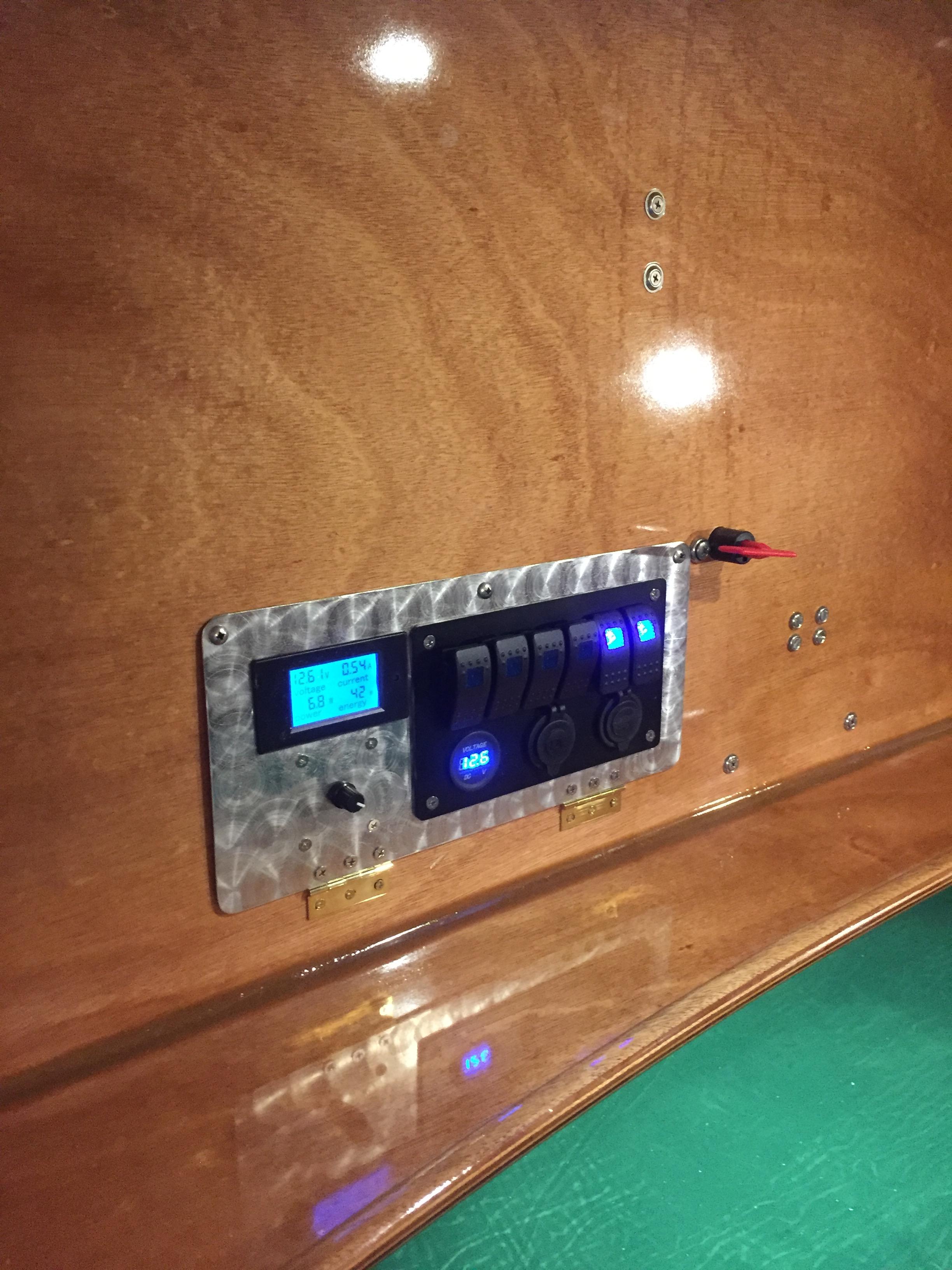
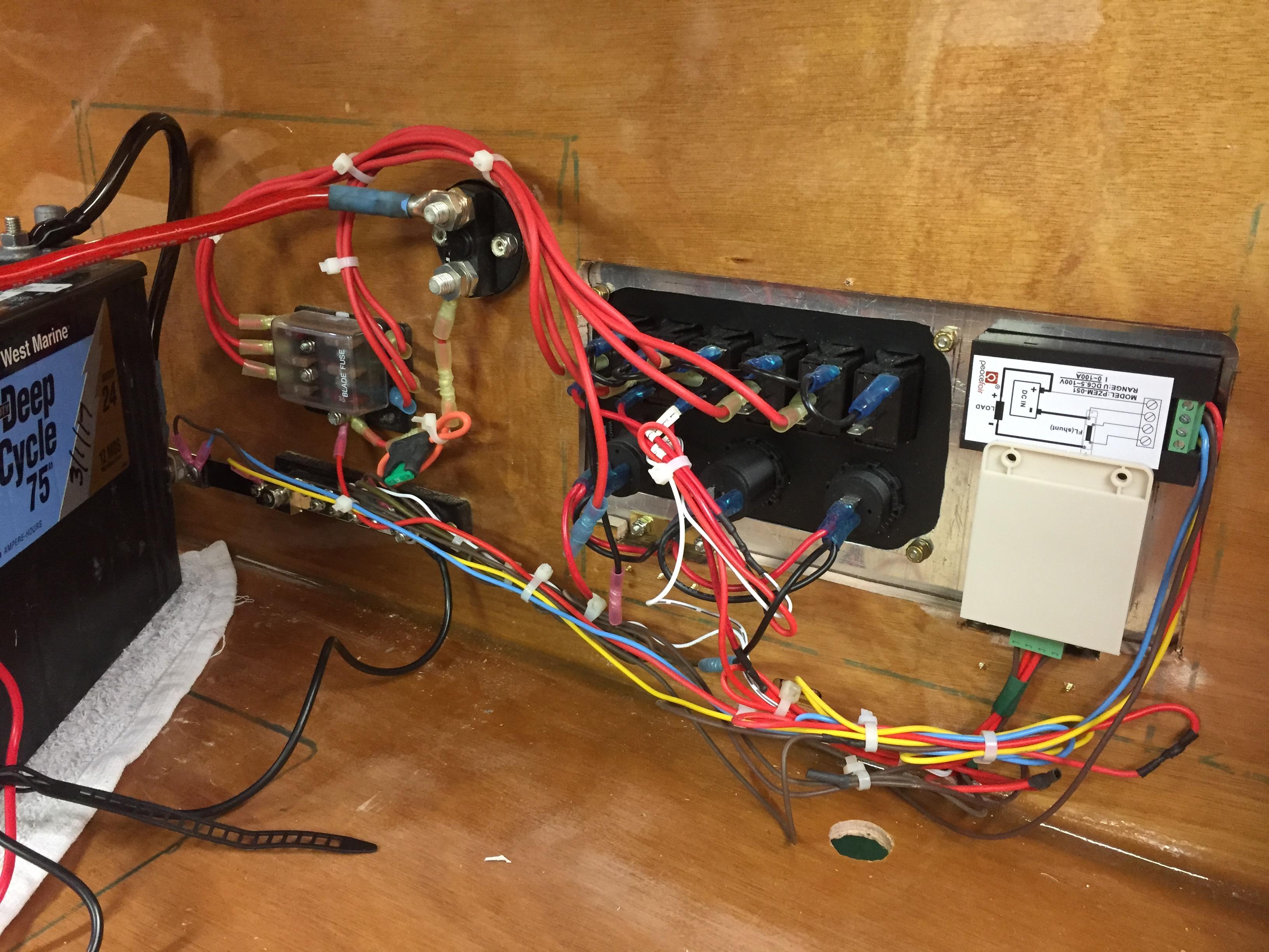
ParticipantI did the electrical install on my camper this week. Starting at the battery, I went to a 6 circuit fuse block I bought on Amazon ( https://www.amazon.com/gp/product/B01GV78UP2/ref=oh_aui_detailpage_o05_s00?ie=UTF8&psc=1 ) for $10, then hopped over from the battery box to the switch panel bay of the galley and hooked each of the six circuits into this ( https://www.amazon.com/gp/product/B01FA0BJKO/ref=oh_aui_detailpage_o02_s00?ie=UTF8&psc=1 ) switch panel, a six gang unit with lighted switches and a volt meter, a cigarette lighter port, and two USB charger ports. I then ran the “hot” lead off of switch #1 to the three LED cabin puck lights, one in each door sill and one screwed into the vent fan trim ring. I had to drill a “through hull” hole for running the wires, I drilled a 3/4″ hole below the shelf into the galley switch panel bay. Later when installing the galley I ended up cutting the galley wood back bottom rail out altogether in the galley switch bay, it was just getting in the way and not doing much structurally.
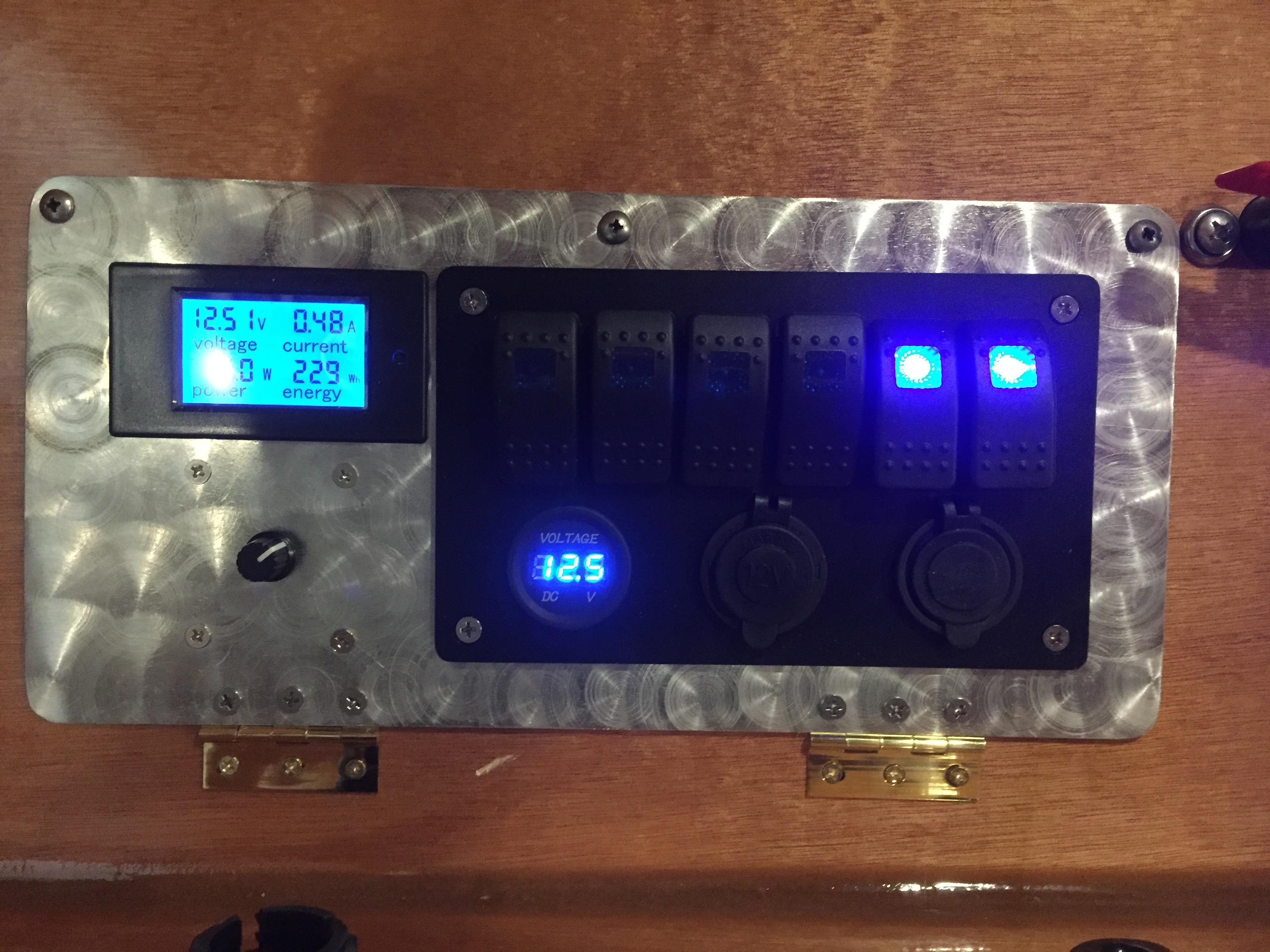
I wanted to be able to dim the cabin lights, so I bought this ( https://www.amazon.com/gp/product/B00IYXGEEQ/ref=oh_aui_detailpage_o08_s00?ie=UTF8&psc=1 ) dimmer for $7 . I also wanted to instrument the electrical system so as to be able to monitor current draw, voltage, etc. I bought this ( https://www.amazon.com/gp/product/B01JOUZELG/ref=oh_aui_detailpage_o03_s00?ie=UTF8&psc=1 ) electrical gauge unit, has volts, amps, watts, and useage functions for $16. Comes with a current shunt that connects between the ground bus bar bought here ( https://www.amazon.com/gp/product/B0091VHLW4/ref=oh_aui_detailpage_o04_s00?ie=UTF8&psc=1 ) for $18 (darn ground bus bar was practically the most expensive electrical system part!!) and the battery negative post.
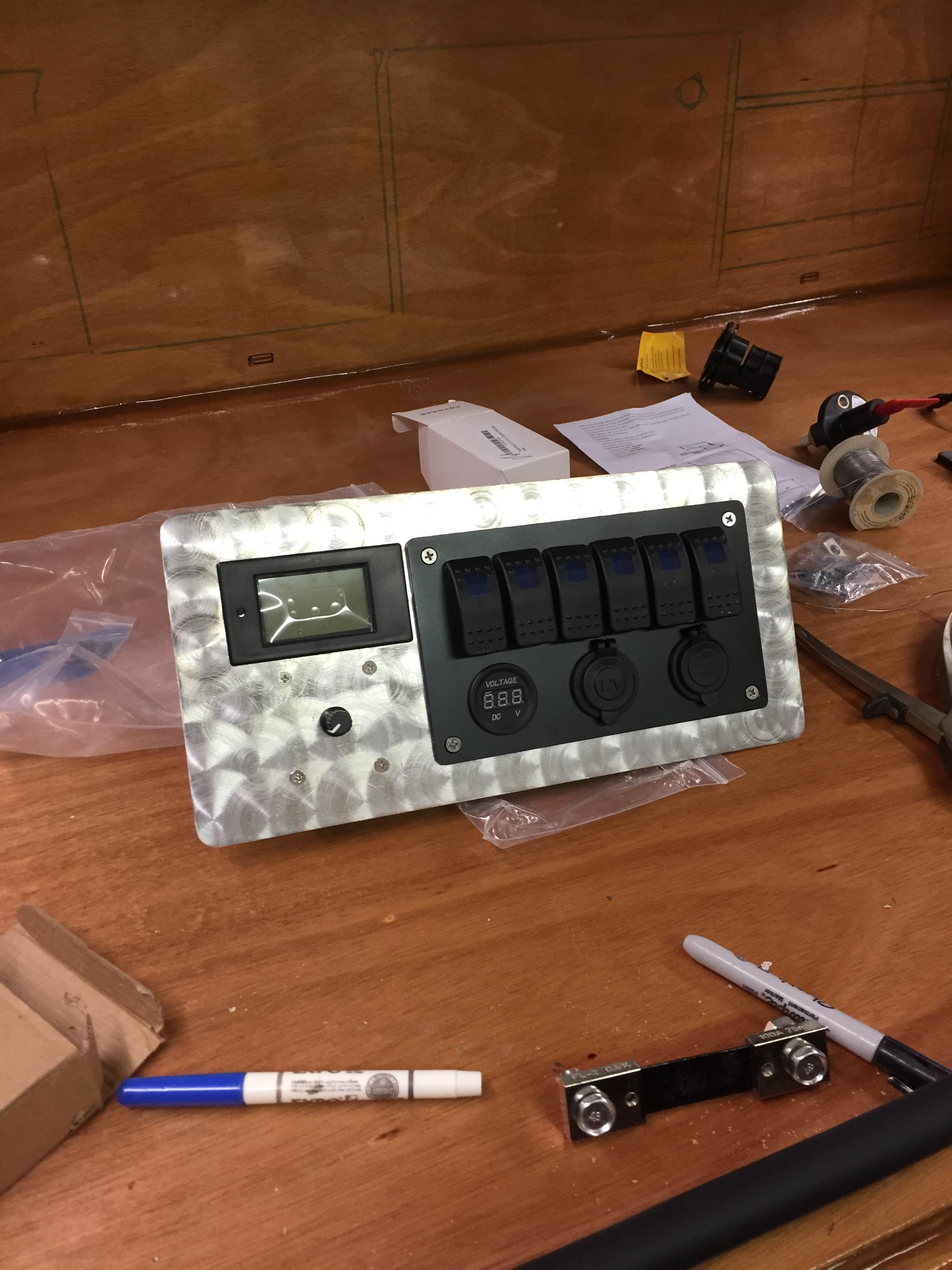
Scratching me head on how to install all this into a 3/8″ thick plywood panel, I decided to build a aluminum sheet metal mounting panel and then just cut a big old hole in the plywood and mount the sheet metal panel to that. I disassembled the switch panel and the dimmer and carefully marked out the mounting hole locations for them and the cutout hole size for the switch panel. The dimmer only needed it’s 4 corner holes and the center knob hole located. The electrical gauge was the most fun as it’s bezel was only about 3/32″ wide to no room for slop on the hole cutout there. I marched the outline onto the sheet metal with a fine tip Sharpie and drilled a starter hole, then used a hand “nibbler ” tool to cut the hole for the gauge. I cut pretty close to the line, then filed the hole to the final fit. Took me an hour and a half but the result was nice.
The surface finish of the aluminum was pretty bad, scratched and such — it was just a piece of scrap when I started. I surface sanded the sheet metal panel on the belt sander with 320 grit belt, kinda going for a brushed metal look. Turned out to be hard to get it nice and even. In hindsight i should have started with a nicer piece of stock. BTW, the aluminum is slightly thinner than 1/16″, maybe 3/64″ thick. Anyway, I had a Scotchbright deburring tool disc thing laying around so I threw that into the drill press and used that to emboss a series of circular scratch marks to emulate “engine turning” pattern. You may have seen this on the Spirit of Saint Louis Charles Lindbergh plane cowling in pictures. In the pic below you see the completed panel and the current shunt. Didn’t take pics of the wiring work but I will have the galley out over the next couple of days for audio system installation and I will get some then to post.
Anyway, cut the big ol’ hole for the panel with a masking tape covered jig saw after carefully working out the location. Oh, here is a tip! I used a “dry erase” marker on the varnished backside of the bulkhead to mark the outlines of the galley bays! I just set the galley in place and drew around the inside of each bay. The dry erase marker comes right off when you are done. This eliminates the “measure everything out and mark” or even using a template. The high tech way would be to use a CAD program to lay it all out. Hint hint— some limited CAD file support from CLC for this would be helpful or at least a printed paper template supplied with the kit! Maybe two or three copies even so builders could use one on the front and one on the back for generating their panel layout.
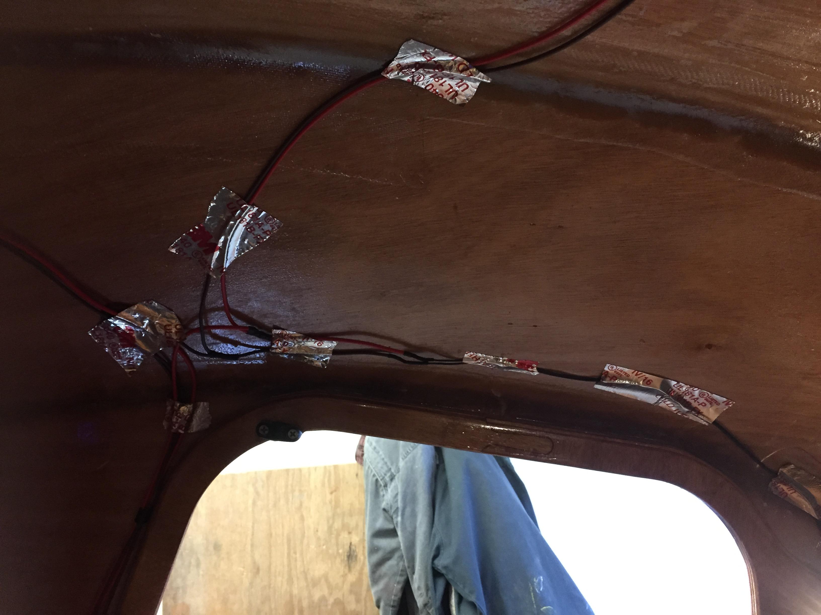
I then ran all the wires for each load circuit, one for the cabin lights, one for the light bar under the shelf, and one for the fan. I found that aluminum dryer vent duct tape worked extremely well for holding wiring in place prior to headliner installation. It’ll all be hidden by the headliner. Each circuit hot lead ran to the switch block and the ground lead ran back to the ground bus bar. Decided to “home run” each circuit ground to make troubleshooting easier should problems arise down the road. I will also photo document the wiring run locations very thoroughly for this reason too.
From the battery positive post I ran a heavy 4 gauge wire to the battery main disconnect switch. I looked at a lot of these and found most of them wanted the big wires on the front side of the panel it attaches to. In the end I found a low end one that would mount from the backside of the panel, it was Che cheapest one of all the ones I looked at but it turned out to be the best one for me. It was about $25. N n From the battery disconnect I ran a heavy 10 gauge wire through a inline fuse to the six circuit fuse block. There is a 30 amp fuse in this main line, not really needed but it’s good to have a master fuse in the system. I used 5 amp circuit fuses plus a couple of 7.5 amp fuses (I ran short of 5 amp fuses). If there is a circuit that is specifically going to draw more current then I would put a larger fuse in that circuit. I think the switches are rated for 20 amps each.
I used the same battery charger that CLC used in their demo camper, it’s a MinnKota MK106-D 6 amp charger. ( https://www.amazon.com/gp/product/B0042T4CM2/ref=oh_aui_detailpage_o01_s00?ie=UTF8&psc=1 ) as well as the MinnKota plug bulkhead panel ( https://www.amazon.com/gp/product/B000MN8RUU/ref=oh_aui_detailpage_o01_s00?ie=UTF8&psc=1 ) . You could easily use something different here. See a local RV supplies store or a marine supply store and see what they have. I just Amazon’ed it because it was easy. I mounted the battery charger onto the front side of the false back galley switch bay and drilled a hole large enough for the charger power cord to pass through. I used a 1″ spade bit and filed the hole a bit but a 1 1/8″ spade bit will be big enough for the cord plug to pass through. Drilled another “through hull” hole in the galley flat deck for the charger card to go to the transom quarter panel.
Enough for now. More pictures of the electrical system tomorrow.
 March 31, 2017 at 10:31 am #693
JakeM
ParticipantLooks good! Where did you get your puck lights? Did they fit into the little cutout on the door frame?
Jake
March 31, 2017 at 11:34 am #694ParticipantAce hardware had the lights, a. Bit pricey at $40 for 3 of them. Damn things wire was marked wrong, wire with the “-” was the positive lead. Backwards. As for fitting, I cut two 2″ diameter wood discs from 3/4 plywood and sanded them to fit in the holes, then flush mounted the pucks. Drilled a 1/8″ or so hole in the door sill “ear” for the wire. Aluminum tape holds the wire in place.
Wire splicing technique: strip 1/2″ of wire on each, twist ends, slide on heat shrink, form into “J”, hook two “J”‘s together. Solder splice. I mostly used a 140 watt soldering GUN, worked well although a iron would work two. The gun is nice since it gives you lots of heat fast. Let splice cool, slide heat shrink over it and hit it with a BIC lighter.
April 1, 2017 at 5:38 pm #698ParticipantSome pix
The hole in the galley flat is for the battery charger power cord.
 April 1, 2017 at 5:50 pm #699Participant
Installing the stereo and the heater today. Yup, heater. Found a 300 watt 12V ceramic heater. Did a test, it draws right at 20 amps, so with a 75 amp/hour battery I should get 3 hours out of it, give or take. Not great but will be nice for knocking the chill off, and I suspect the small cabin volume will mean I won’t have to run it for more than maybe 20 minutes at a time, maybe less.
So, cutting big ol’ holes for the speakers and generating mounts for the head unit. Looked hard at the round gauge style radios and went with a single-DIN conventional unit. Mounting isn’t that hard and mucho better features. Doing Polk Audio 6 1/2″ cabin speakers and 4″ galley speakers. I’ll use the front/rear fader controls to route sound inside or outside as needed.
June 25, 2019 at 9:54 am #2533Anonymous
InactiveI never tried such kind of installation by own because my friend is an electrician and he can do all the work of installation for me.
August 16, 2020 at 9:47 pm #3175jklancke
ParticipantSOMDTD, any chance you have your wiring diagramed out so I might be able to follow it as a base to my system?
Thanks
Jeff
-
AuthorPosts
- You must be logged in to reply to this topic.